PROJECT
The wonderful, whimsical world of automata

Charles Mak

Find more Gifts / Crafts projects
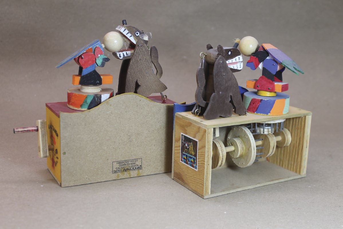
Sculpt a miniature woodworker that springs to life at the turn of a crank.
In the woodworking world, automata are self-operating mechanisms or objects that follow a set sequence of movements when operated. The word kinetic is also used to describe some moving woodworking projects or sculptures.
Constructing a mechanical build like this may sound daunting, given the need for the coordinated movements of all of its parts. I’ll show you a simple kinetic piece here to introduce you to this enjoyable part of woodworking. If you want a break from your usual projects, build this woodturner and let it work at your command – and to the delight of those who encounter it.
The kinetic woodturner comprises four key components: the workbench that houses the mechanical parts; the mechanism; the mini-lathe; and the woodturner. Very much like building a cabinet or table, we’ll build each key part and then put them together at the end.
A project like this is typically a bit less constrained by precise dimensions than most other woodworking projects. Pieces of scrap can often play a large role in determining the size of a workpiece. Having said that, to give you some idea of the sizes of the parts in this project, the workbench is 8″ long × 3″ wide × 5″ high. The drive shaft is made from 1/4″ diameter dowel that’s 4″ long. The lathe is 3-1/2″ long × 2″ high, the torso is 5″ high, the left leg is 3″ long and the head is about 1″ deep × 1-1/4″ wide.
I created most of the wooden parts you see here, but you can also find good sources of readymade parts to purchase online. Circular disks can act as pulleys while long dowels are an easy way to create simple shafts. Once you start looking, I’m sure you’ll find lots of small manufactured parts from Canadian suppliers that could be incorporated into your next kinetic sculpture or project.
The wonderful, whimsical world of automata
Level of detail
The scope of an automaton project can be adjusted to suit your wants. If you want to build a simple sculpture, one could surely be made in a day. But if you want to spend time carefully shaping the parts and including lots of detail, the same sized project could take a week or more to complete.
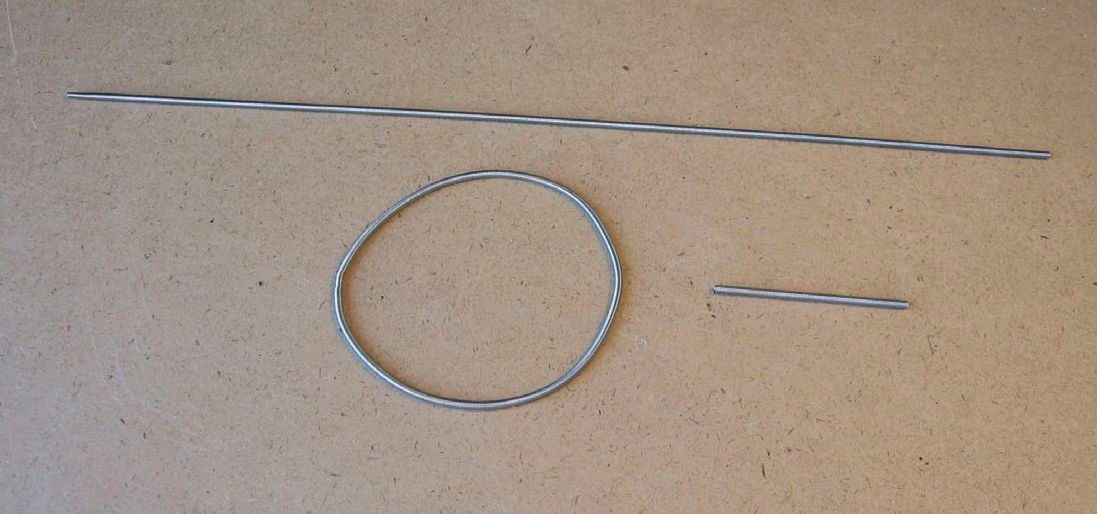
The drive belt
Although you could use a simple elastic band, another option is a flexible drive belt. These belts are typically used on model steam engines. Although there may be multiple sources, searching on Amazon and eBay are good places to start. The drive belts are made of spring wire and their ends can be twisted together to form a loop in the dimension you need.
The wooden “dowel hinge”
Some of these parts need to be joined together, but still allow for some movement between them. The left leg-to-body joint is a perfect example. The left leg gets screwed to the rear edge of the workbench, and the body gets attached on top of the left leg with a 3/32″ diameter wood dowel that protrudes into both parts and gets glued in place. I’m calling this a “dowel hinge”, because it holds the joint together, but also allows a small amount of movement to occur between the left leg and the body.
This joint isn’t overly strong, but it doesn’t need to be. If a larger dowel were used the joint would be stronger, but it wouldn’t allow for any movement in this kinetic project. You can play around with this joint; leaving a small gap between the two parts will provide more movement. This can be adjusted by using a different length of dowel, so it bottoms out in both of the holes, while not allowing the parts to come into contact with each other. A larger project may need a larger diameter dowel.
The miniature workbench
The mini bench consists of the top, two side panels, a shelf and two support cleats. For this build, I opted for very simple joinery. I chose brad nail-reinforced butt joints that were glued. There’s nothing wrong with going all out and fixing the parts that make up the workbench with sliding dovetails or other joints. Having said that, machining joints on smaller workpieces poses a unique challenge. One approach is to do all the machining while the workpieces are still part of a larger blank, then cut the workpieces to final size.
I first cut a slot in the top to allow the drive belt to pass through the workbench top and turn the lathe. Next, I drilled a hole on the right side to allow the drive shaft to extend through the side. The diameter of the hole should allow the drive shaft to rotate smoothly, but with no slop. I glued up the workbench and added a couple of brads to reinforce the butt joint. Some scrap blocks were glued to the top to hide the brads.
The mechanism
I chose a crank slider and pulley as the mechanism. The crank slider is simply a cam with an arm (a wire attached to an offset screw) that pulls and pushes the woodturner’s body while the pulley spins the turned object.
First, I made the crank handle and cam shaft by cutting and gluing dowels (one short and one long) to a rectangular piece. I made the cam and the collet out of two 1-1/4″ diameter discs with a 1/4″ diameter centre hole, then drove a small screw into the cam 1/4″ from the centre point. Make sure to bore pilot holes in these small pieces, as they’re otherwise very likely to split. After dry-fitting, I put them aside for assembly and gluing later.
To make the drive belt, I cut the wire to 8″ long and then joined the ends. You could also just leave the final length uncut for now and take care of that when the entire project comes together. It may be easier to determine just how long it needs to be at that point.
The mini-lathe
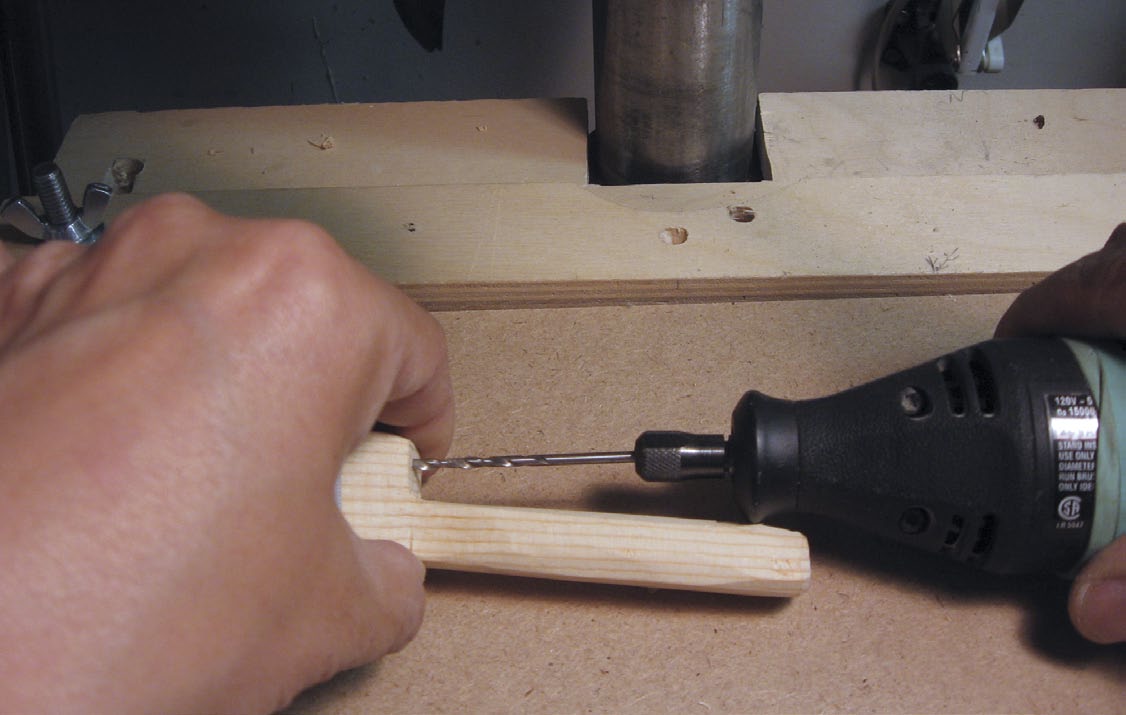
On a lathe, turn a spindle for the turned object. When designing your spindle, remember the scale is quite small, so keep the beads, coves and other details on the smaller side. Trim this spindle to a length of 2″ and drill a 1/8″ diameter centre hole end-to-end.
I used the bandsaw to cut out most of the mini-lathe from a single block of wood. You could also make the lathe from multiple smaller parts, if you wanted. The initial cuts to create the shape were easy, but I eventually turned to a hand saw to further refine the shape of the lathe. I then glued a wooden tool rest to the lathe bed as well as a dowel painted black to the lathe as the motor.
The pulley system was made out of a wood spool, dowel rod and retaining button. Again, these parts can be shop-made, but there’s also nothing wrong with purchasing these parts. After drilling two holes in the lathe to accept the pulley system, I assembled the spindle on the lathe with the pulley. The lathe was glued in position on the workbench top so the pulley aligns with the centre of the slot that was cut into the top.
The woodturner
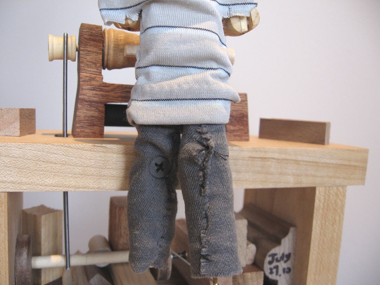
The woodturner figure is the last component to make, and consists of the head, the body with the rigid left leg, the hinged two-part right leg and the arms, all to be connected to each other by 3/32″ diameter pieces of dowel to form each dowel hinge.
After cutting out the head as well as the body / right leg assembly on the bandsaw, I drilled all the holes on the part and glued the head to the torso with a dowel hinge. At this point I attached a screw eye to the end of the right leg. This screw eye would eventually be attached to the rotating mechanism with wire. Next, the left leg was cut and the dowel hinge holes were drilled before I countersunk the 1/8″ diameter screw hole so the leg could be attached to the rear edge of the workbench.
I cut out the arms, cut the simple elbow joints with a hand saw and drilled holes at the elbows. A skew chisel was made out of a small piece of metal and a dowel rod. Some of these small accessories can be made from materials that can commonly be found around the home. The elbow joints were then glued and left to dry before joining them to the torso. Next, the torso was mounted on the left leg, all with dowel rods without glue. The lack of glue allows the torso to rotate slightly when the crank is being turned.
Instead of painting the figure, my daughter sewed some fabric to dress up the woodturner and I glued the skew handle to the right hand. While doing all this, I kept in mind where the hands of the figure should finish so it would look like it was actually working on a lathe.
The final assembly
I screwed the woodturner’s left leg to the back edge of the bench top. After feeding the drive belt to the pulley, I glued the crank slider in place and glued some scrap blocks to the shelf for decoration. Lastly, I tied a wire connecting the screw on the cam to the screw eye on the end of the turner’s right leg.
Sanding the surfaces smooth, as well as adding a small amount of paste wax on some of the rotating surfaces help the parts move freely.
After testing all the movements of the piece, I glued only the joints in the shoulders, leaving the elbows and the torso free to turn. You’re done – crank it, and turn some heads!
Lots of Automata Options
Automata have been around for thousands of years. It’s easy to see why this type of object still exists today, as they’re not only fascinating to watch, but they’re also fun to design and build. When it comes to designing an automaton, there are many approaches to do so. The simple automaton described in this article includes a single drive shaft that moves two other parts when it’s cranked, but there are many other ways to design a project of your own. To give you a sense of what else is possible, here are a few other automata Mak has built in the past.
Anubis Pushups – Modelled after British Paul Spooner’s design, but executed with a simpler mechanism, this kinetic toy mimics the action of a human doing pushups as the handle is cranked.

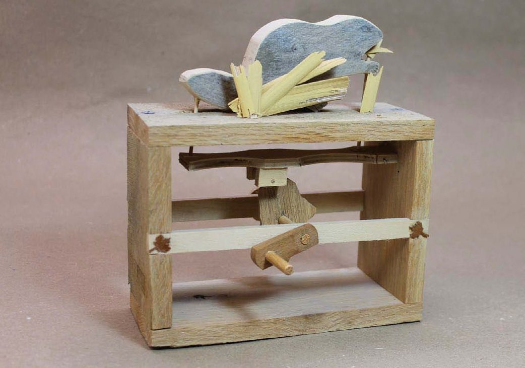
Canadiana Automaton – This mechanical sculpture of Mak’s own design features a beaver, a national symbol of Canada, and a cam in the form of an outline map of Canada. When the handle is turned, it shows the beaver gnawing and chewing on a plant, while slapping its tail.
Lion Tamer – This is a much more complex automaton, based on Ron Fuller’s design. Turning the handle causes the lion to open its mouth, trying to bite off the tamer’s head, but the tamer quickly turns around and escapes at every turn.
Photos by Charles Mak
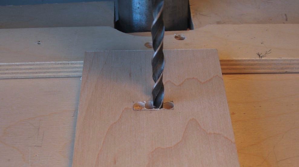
A Simple Mortise
A mortise in the workbench top is needed so the drive belt can pass between the lathe and the operating mechanism. Mak chose to remove most of the waste for the mortise with a drill press, then used a chisel to square up the mortise.
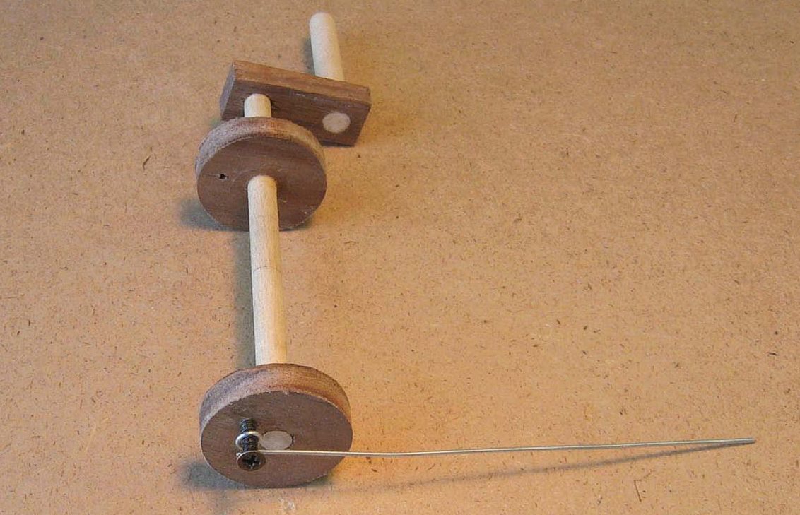
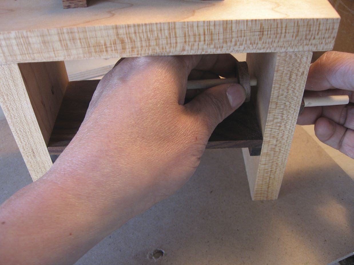
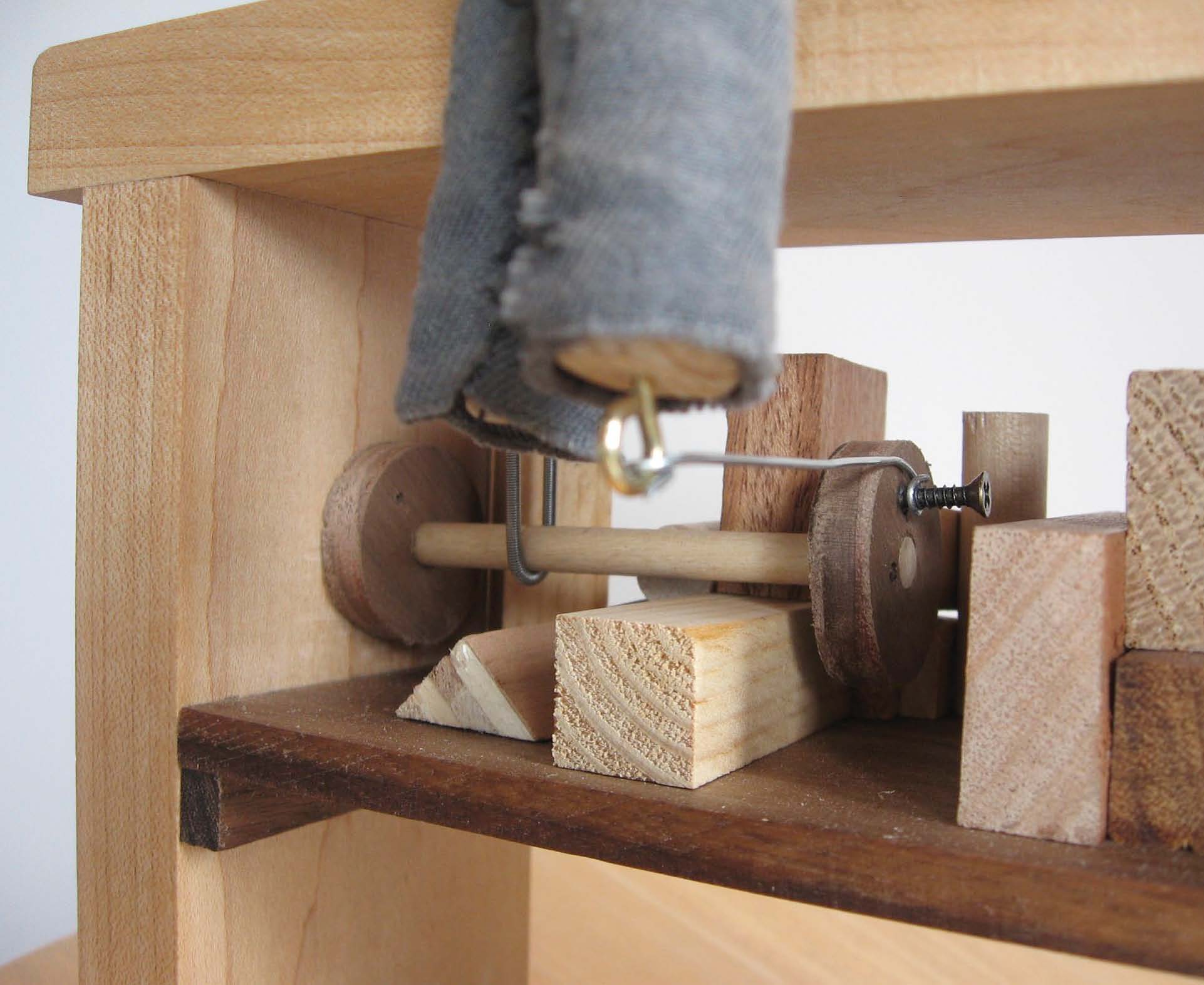
The Mechanism
The drive shaft, coupled with an operating handle, allows the user to add movement to this project. A wooden washer sandwiches the drive shaft to the right side of the workbench base and an identical part gets attached on the end of the drive shaft. A small screw gets attached to the second washer offset from the centre, providing movement to the right leg of the woodturner.
The Drive Belt
A drive belt can be purchased and cut to length so it connects the crank mechanism to the lathe. One end of the drive belt can be attached to the other by twisting them together.
“Dowel Hinge” Holes
Mak uses a drill bit to bore a hole in the torso / right leg combination, so the left leg and torso can fit together.
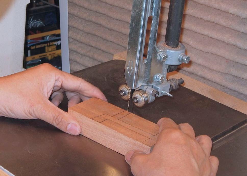
The Lathe
Mak roughs the lathe out on the bandsaw from a single piece of wood. It’s also possible to make the lathe from multiple workpieces, though it makes the task more complex.
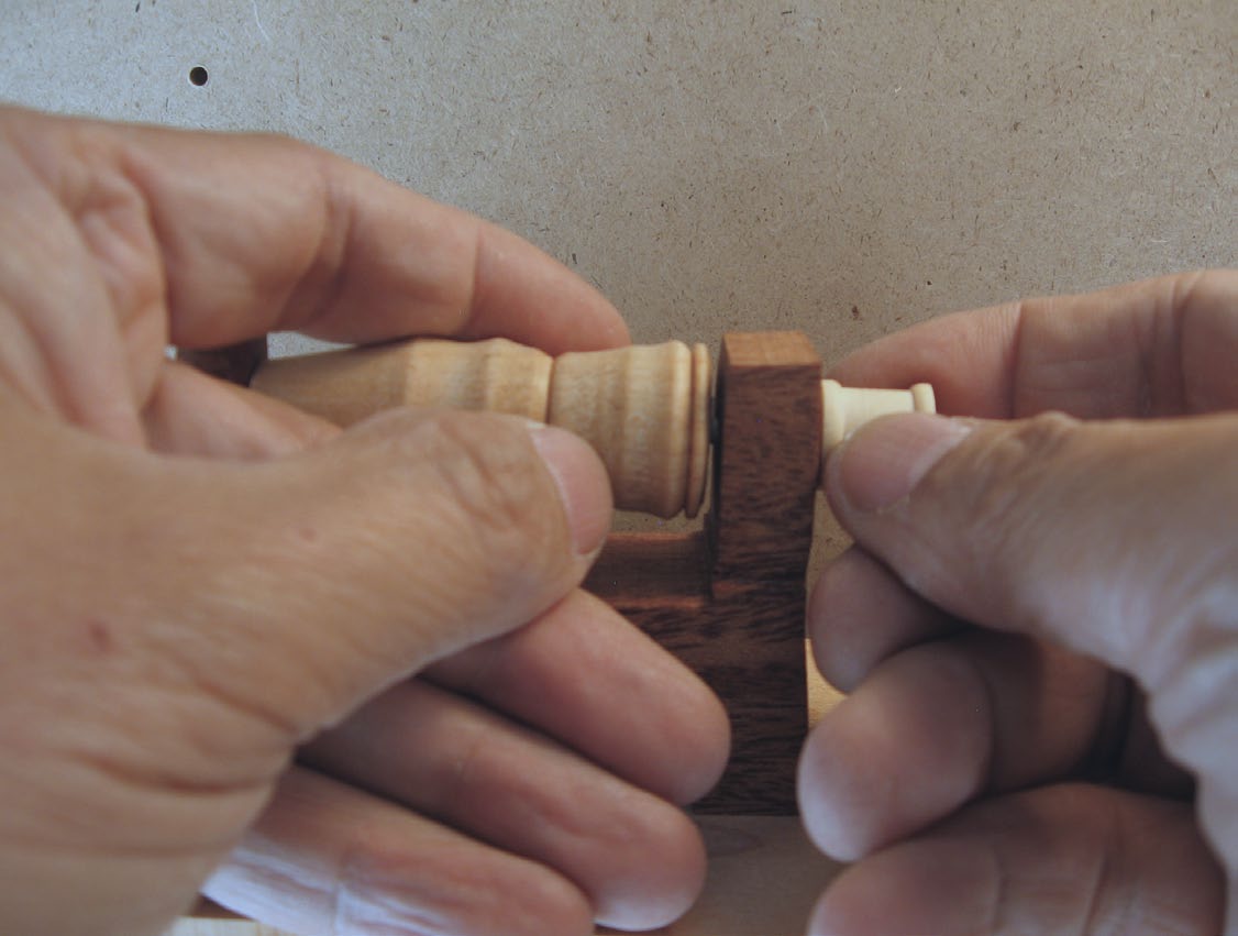
Fasten the Turning
Once the turning is complete, and a hole has been bored through it, it can get fastened to the lathe with the pulley and retaining button. The friction should be low enough to allow the assembly to rotate easily.
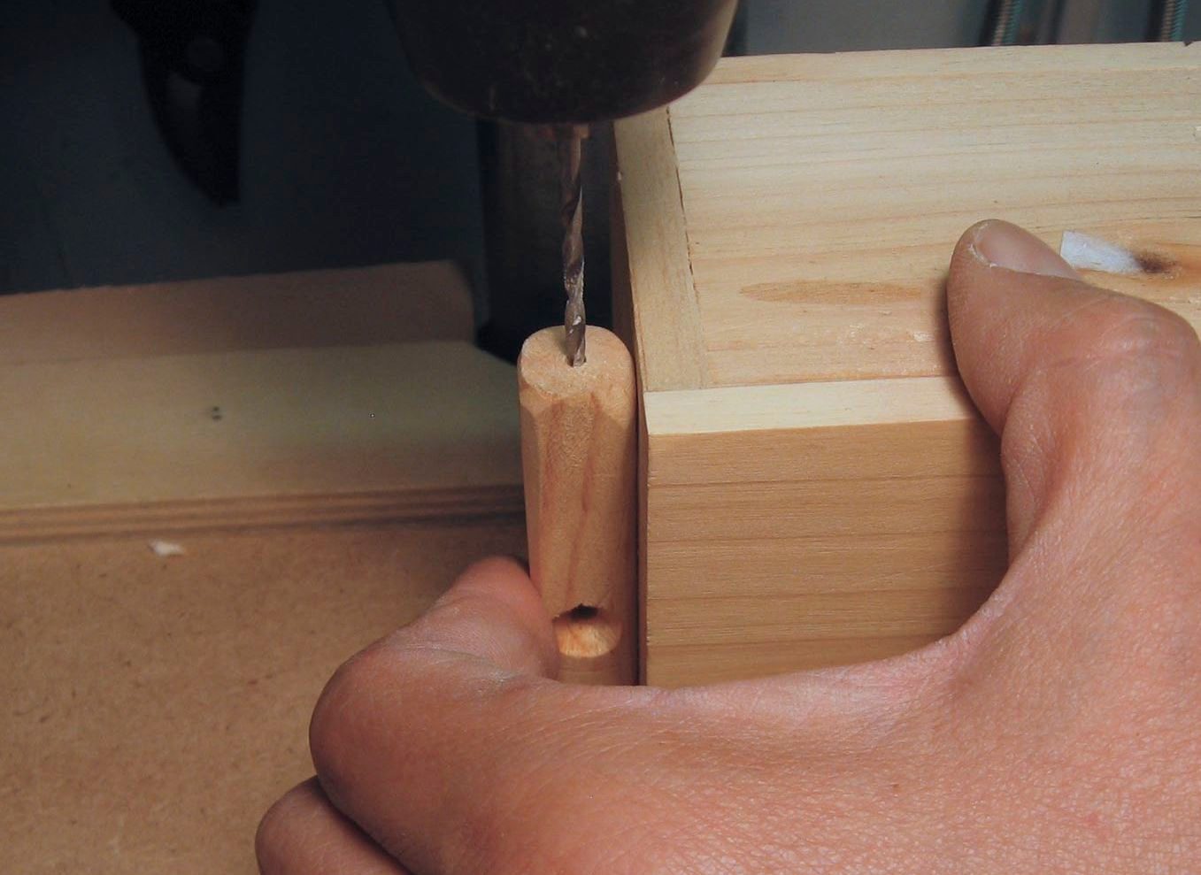
Drill It Straight
To ensure the hole in the top of the left leg is drilled accurately, Mak presses it against a small box while boring the hole.
Secure a Leg
Although it looks painful, a screw driven through the left leg keeps it fixed to the rear edge of the workbench top. The torso is otherwise free to move slightly when the crank is rotated.
Wooden Washer
The wooden washer on the inner surface of the workbench side keeps the mechanism assembly in place while it’s being rotated. It gets glued into place.
Add the Wire
A piece of wire is attached between the screw eye in the turner’s right foot and the small offset screw in the mechanism. This connection provides some movement to the woodturner when the crank is rotated.
[illustrations_gallery]